A ray tracer emits a ray from each pixel toward the scene to determine the color of the pixel. The process of computing the color can be split into three parts:
- Ray generation: The origin and direction of each pixel ray are computed.
- Ray intersection: The ray finds the closest object intersecting the viewing ray.
- Shading: The intersection point, surface normal, and other information are used to determine the color of the pixel.
A ray can be represented with a 3D parametric line from the eye $\mathbf{e}$ to a point $\mathbf{s}$ on the image plane as:
Note that:
- $\mathbf{p}(0) = \mathbf{e}$
- $\mathbf{p}(1) = \mathbf{s}$
- If $0 < t_1 < t_2$, then $\mathbf{p}(t_1)$ is closer to $\mathbf{e}$ than $\mathbf{p}(t_2)$.
- If $t < 0$, then $\mathbf{p}(t)$ is behind $\mathbf{e}$.
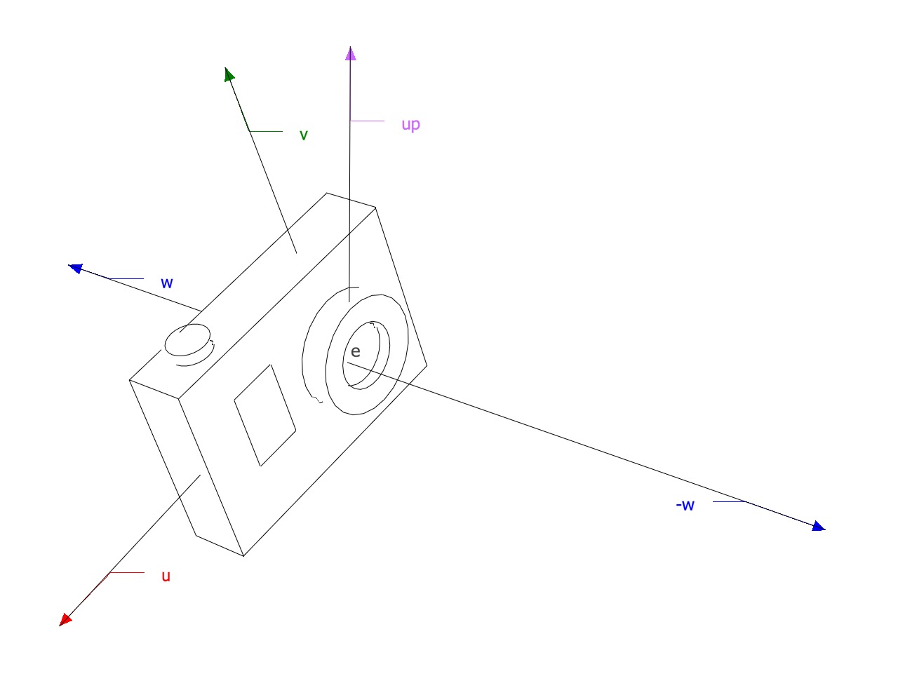
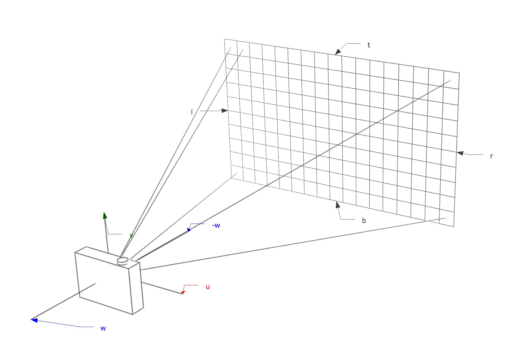
Camera Coordinate System
All the rays start from the origin of an orthonormal coordinate frame known as the camera/eye coordinate system. In this frame, the camera is looking at the negative $\mathbf{w}$ axis.
Camera
The coordinate system is built from:
- The viewpoint $\mathbf{e}$, which is at the origin of the camera coordinate system.
- The view direction, which is $\mathbf{-w}$.
- The up vector, which is used to construct a basis that has $\mathbf{v}$ and $\mathbf{w}$ in the plane defined by the view direction and the up vector.
Ray Generation
Pixel Coordinates
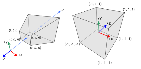
The image dimensions are defined with four numbers:
- $l, r$: the position of the left and right edges.
- $t, b$: the position of the top and bottom edges.
Note that the coordinates are expressed in the camera coordinate frame defined in a plane parallel to the $w=0$ plane (the $w=0$ plane is defined by the point $\mathbf{e}$ and the vectors $\mathbf{u}$ and $\mathbf{v}$).
The image has to be fitted within a rectangle of $n_x \times n_y$ pixels. For example, the pixel $(0,0)$ has the position $(l + 0.5 \tfrac{r - l}{n_x}, b + 0.5 \tfrac{t - b}{n_y})$. Note that the half-pixel measurement times pixel-dimension is because of the way a pixel is defined (see rendering ). A pixel with coordinates $(x, y)$ will have the position:
Orthographic View
For an orthographic view, all the rays will have the direction $-\mathbf{w}$. There isn’t a particular viewpoint; however, we can define all the rays to be emitted from the $w=0$ plane using the pixel’s image-plane position as the ray’s starting point.
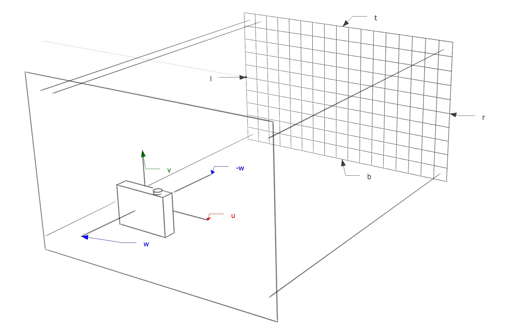
Orthographic View
Perspective View
For a perspective view, all the rays will have the same origin $e$, but the image-plane is not located at $w=0$ but at some distance $d$ in the $-\mathbf{w}$ direction. This time, each ray will have a varying direction based on the location of the pixel’s image-plane position with respect to $e$.
Perspective View
Ray Intersection
Once a ray in the form $\mathbf{e} + t\mathbf{d}$ is generated, we find the first intersection with an object where $t > 0$. Whenever there are many objects that intersect a ray, the intersection point with the lowest $t$ is returned.
The following pseudocode tests for “hits”:
ray = e + td
t = infinity
for each `object` in the scene
  if `object` is hit by `ray` and `ray's t` < `t`
    hit object = `object`
    t = `ray's t`
return hit t < infinity
Shading
Once the visible surface is known, the next step is to compute the value of the pixel using a shading model, which can be made out of simple heuristics or elaborate numeric computations.
A shading model is designed to capture the process of light reflection on a surface. The important variables in this process are:
- $\mathbf{p}$ (intersection point) - the intersection point between a surface and a ray.
- $\mathbf{l}$ (light direction) - a unit vector pointing from the surface towards a light source, computed by normalizing the vector between the intersection point $\mathbf{p}$ and the light source position $\mathbf{l_s}$.
- $\mathbf{v}$ (view direction) - a unit vector pointing from the surface towards the place the ray is emitted from. It’s computed by normalizing the vector between the intersection point $\mathbf{p}$ and the ray origin $\mathbf{ray_{origin}}$.
- $\mathbf{n}$ (surface normal) - a unit vector perpendicular to the surface at the point where the reflection is taking place.
- Other characteristics of the light source and the surface, depending on the shading model.
Lambertian Shading
One of the simplest shading models, discovered by Lambert in the 18th century. The amount of energy from a light source that falls on a surface depends on the angle of the surface to the light.
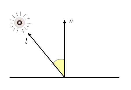
Lambert
- A surface facing directly the light receives maximum illumination.
- A surface tangent to the light receives no illumination.
- A surface facing away from the light receives no illumination.
Thus, the illumination is proportional to the cosine of the angle between $\mathbf{n}$ and $\mathbf{l}$, i.e., $\mathbf{n \cdot l} = \cos{\theta}$. The color of the pixel is then:
Where:
- $k_d$ is the diffuse coefficient, a characteristic of the surface.
- $I$ is the intensity of the light source.
Additional notes of this model:
- The model is view-independent.
- The color of the surface appears to have a very matte, chalky appearance.
Blinn-Phong Shading
Many surfaces show some degree of highlights (shininess) or specular reflections that appear to move as the viewpoint changes. The idea is to produce reflections when $\mathbf{v}$ and $\mathbf{l}$ are positioned symmetrically across the surface normal.
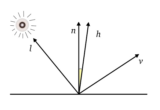
Blinn-Phong
- The half vector $\mathbf{h}$ is a unit vector that goes through the bisector of the angle between $\mathbf{v}$ and $\mathbf{l}$.
Also:
- If $\mathbf{h}$ is near $\mathbf{n}$, then the specular component should be bright; if it’s far away, it should be dim. Therefore, the illumination is proportional to the cosine of the angle between $\mathbf{n}$ and $\mathbf{h}$, i.e., $\mathbf{n \cdot h} = \cos {\theta}$.
- The specular component decreases exponentially when $\mathbf{h}$ is far away from $\mathbf{n}$. Therefore, the result is taken to the $p$ power, $p > 1$, to make it decrease faster.
The color of the pixel is then:
Where:
- $k_s$ is the specular coefficient, a characteristic of the surface.
- $I$ is the intensity of the light source.
- $p$ is a variable that controls how fast the result decreases.
Note that the color of the pixel is the overall contribution of both the Lambertian shading model and the Blinn-Phong shading model.
Ambient Shading
Surfaces that receive no illumination are rendered completely black. To avoid this, a constant component is added to the shading model. The color depends entirely on the object hit, with no dependence on the surface geometry.
Where:
- $k_a$ is the surface ambient coefficient.
- $I_a$ is the ambient light intensity.