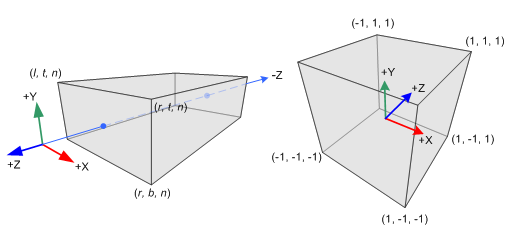
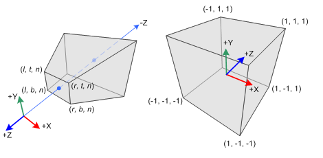
The canonical view volume is a cube with its extreme points at [-1, -1, -1] and [1, 1, 1]. Coordinates in this view volume are called normalized device coordinates (NDC). The objective of this step is to build a transformation matrix so that a region of space we want to render, called the view volume, is mapped to the canonical view volume.
Some points expressed in view space won’t be part of the view volume and will be discarded after the transformation. This process is called clipping (we only need to check if any coordinate of a point is outside the range [-1, 1] to discard it).
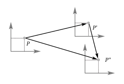
Later, it’ll be seen that both transformations imply division, and a neat trick is the use of projective geometry to avoid division. Any point that has the form (\alpha x, \alpha y, \alpha z, 1) can be represented as (x, y, z, \tfrac{1}{\alpha}) in homogeneous coordinates. So, we can introduce an intermediate step that transforms the points to clip coordinates and then to normalized device coordinates by doing a division with the $w$-coordinate: $\tfrac{1}{1/\alpha} = \alpha$.
Orthographic Projection
An orthographic projection matrix is built with six parameters:
- left, right: planes in the $x$-axis
- bottom, top: planes in the $y$-axis
- near, far: planes in the $z$-axis
These parameters bound the view volume, which is an axis-aligned bounding box.
Orthographic Projection
Since the mapping of the range $[l, r]$ to the range $[-1, 1]$ is linear, we can use the equation of the line $y = mx + b$ and find the values of $m$ and $b$. However, we can intuitively get a similar equation by creating a function $f(x)$ so that $f(0) = -1$ and $f(1) = 1$. We can create a nested function $g(x)$ so that $g(l) = 0$ and $g(r) = 1$ (note that $[l, r]$ is the input range). Then $f(x)$ has the form:
Finally, $f(x)$ has the form:
We can adapt \eqref{linear-mapping} to have a similar form for the y-coordinate using $t$ and $b$. These equations are transformations from view space to clip space:
The $z_{clip}$ value will be different from the ones above since we’re mapping $[-n, -f] \Rightarrow [-1, 1]$:
The $w$ is left untouched since the projection doesn’t imply division. The general orthographic projection matrix is:
The transformation matrix from view space to clip space is:
Finally, note that $w_{clip}$ will always have the value of $w_{view} = 1$. Therefore, the transformation to NDC will not modify the coordinates:
Building the Matrix Using Combined Transformations
A simpler way to think about this orthographic projection transformation is by splitting it into three steps:
- Translation of the bottom-left-near corner to the origin, i.e., $[l, b, -n] \rightarrow [0, 0, 0]$.
- Scale it to be a 2-unit length cube.
- Translation of the bottom-left corner from the origin, i.e., $[0, 0, 0] \rightarrow [-1, -1, -1]$.
Perspective Projection
Projective geometry concepts are used in this type of projection, particularly the fact that objects away from the point of view appear smaller after projection. This type of projection mimics how we perceive objects in reality.
A perspective projection matrix is built with six parameters: left, right, bottom, top, near, far.
- left, right: $x$-axis bounds for the near plane.
- bottom, top: $y$-axis bounds for the near plane.
- near, far: planes in the $z$-axis. The intersection point of the line passing through the origin parallel to the vector $[l,b,-n]$ and the plane far is the bottom-left-far extreme of the view volume. A similar logic is used to find all the extremes in the far plane of the view volume.
These parameters define a truncated pyramid, also called a frustum .
Perspective Projection
General Perspective Projection Matrix
The mapping of the range $[l,r]$ to the range $[-1,1]$ can be split into two steps:
- Project all the points to the near plane. This way, all the $x$- and $y$-coordinates will be inside the range $[l,r] \times [b,t]$.
- Map all the values in the range $[l,r]$ and $[b,t]$ to the range $[-1, 1]$.
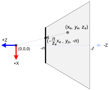
Top view of the frustum
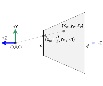
Side view of the frustum
Let $\mathbf{v}_{view}$ be a vector in view space which is going to be transformed to clip space. By similar triangles, we see that the value of $x_p$ and $y_p$ (the coordinates projected to the near plane) is:
Note that both quantities are inversely proportional to $-z_{view}$. What we can do is manipulate the coordinate so that it has a common denominator:
The point in homogeneous coordinates is:
OpenGL will then project any 4D homogeneous coordinate to the 3D hyperplane $w=1$ by dividing each of the coordinates by $w$. Note that this division operation isn't done by the application but by OpenGL itself in a further step on the rendering pipeline.
We can take advantage of this process and use $-z_{view}$ as our $w$. With this in mind, we can construct a transformation matrix so that transformed points have $w = -z_{view}$:
Where $x_{clip}, y_{clip}, z_{clip}, w_{clip}$ are expressed in terms of the clip space. When each coordinate is divided by $w_{clip}$, we’ll have NDC:
Next, $x_p$ and $y_p$ are mapped linearly to $[-1,1]$. We can use the function to perform linear mapping \eqref{linear-mapping}:
Next, we substitute the values of $x_p$ \eqref{projection-near} in $x_{ndc}$ \eqref{ndc-near}:
Note that the second fraction is manipulated so that it’s also divisible by $-z_{view}$. Also, note that the quantity in the parenthesis is in clip space coordinates: $x_{clip}$.
Similarly, the value of $y_{clip}$ is:
Then the transformation matrix seen in \eqref{pm1} is now:
Next, we need to find the value of $z_{clip}$. Note that the projected value is always a constant because the $z_{clip}$ component depends on $z_{view}$ and is also divided by $-z_{view}$. We need $z_{clip}$ to be unique for the clipping and depth test. Plus, we should be able to unproject it (through an inverse transformation).
Since $z_{ndc}$ doesn’t depend on $x_{view}$ or $y_{view}$, we can borrow the $w$-coordinate to find the relationship between $z_{ndc}$ and $z_{view}$. With that in mind, we can make the third row of \eqref{pm2} equal to:
Then $z_{ndc}$ has the form:
Since $w_{view}=1$ in view space:
Note that the value is not linear, but it needs to be mapped to $[-n, -f] \mapsto [-1,1]$. Substituting the desired output range $[-1, 1]$ as $z_{ndc}$, we have a system of equations:
Subtracting the second equation from the first:
Solving for $B$ given $A$:
Substituting the values of $A$ and $B$ in \eqref{pm3}, we have the general perspective projection matrix:
Symmetric Perspective Projection Matrix
If the viewing volume is symmetric, i.e., $r = -l$ and $t = -b$, then some quantities can be simplified:
Then \eqref{pm4} becomes:
Symmetric Perspective Projection Matrix from Field of View/Aspect
gluPerspective
receives, instead of the $x$ and $y$ bounds, two arguments:
- field of view ($fov$), which specifies the field of view angle in the $y$ direction.
- aspect ($aspect$), which is the aspect ratio that determines the field of view in the $x$ direction, calculated as $\tfrac{x}{y}$. The value is commonly $\tfrac{screen\ width}{screen\ height}$.
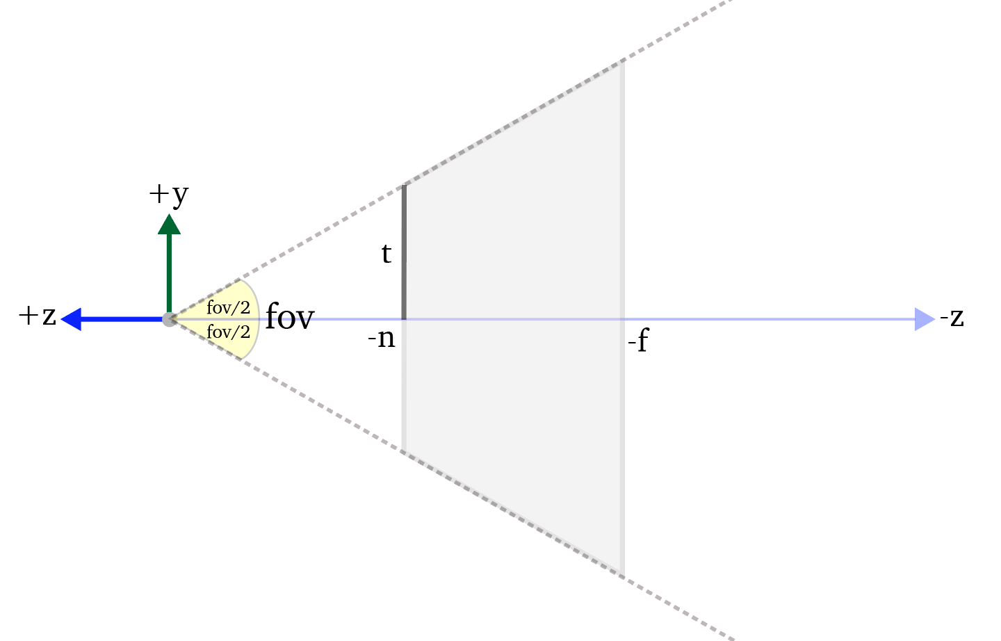
fov
We see that the value of $t$ (top) is:
We can find the value of $r$ (right) with the aspect ratio:
Substituting \eqref{fov-t} and \eqref{fov-r} in \eqref{pm5}: