
The view transform maps every point in the scene from world space to view space:
$$ \mathbf{v}_{\text{view}} = \mathbf{M}_{\text{view}} \mathbf{v}_{\text{wld}} $$
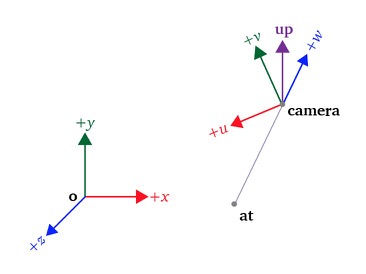
In view space the camera sits at the origin, so the transform is fully defined by three parameters:
- $\mathbf{camera}$: the camera position in world space.
- $\mathbf{at}$: the point in world space the camera looks toward.
- $\mathbf{up}$: the camera’s upward direction, typically the positive $y$-axis.
View Transform
The view matrix is built in two parts: first the camera frame $(\mathbf{u}, \mathbf{v}, \mathbf{w})$ is constructed from these parameters, and then the world is transformed so that the frame aligns with the canonical axes.
(For how matrix composition works and why the order of multiplication matters, see Combining Matrix Transformations .)
Building the Camera Frame
The view matrix must encode the camera’s orientation, not just its position. The camera’s orientation is captured by an orthonormal basis expressed in world coordinates:
- $\mathbf{w}$: points from the target $\mathbf{at}$ toward the camera, so the camera looks along $-\mathbf{w}$, the negative $z$-axis of view space.
- $\mathbf{u}$: the camera’s right direction.
- $\mathbf{v}$: the camera’s upward direction.
These three unit vectors, together with the camera position (the eye $\mathbf{e}$ of the next section), become the columns of the frame-to-canonical matrix derived below. This is why they must be unit length and mutually perpendicular: the resulting matrix is orthonormal, so its inverse is its transpose, which is how $\mathbf{R}^T$ enters the view matrix.
Given $\mathbf{camera}$, $\mathbf{at}$, and $\mathbf{up}$, the basis is computed as follows:
- $\mathbf{w}$ is the normalized vector from $\mathbf{at}$ to $\mathbf{camera}$:
$$ \mathbf{w} = \frac{\mathbf{camera} - \mathbf{at}}{\lVert \mathbf{camera} - \mathbf{at} \rVert} $$
- $\mathbf{u}$ is the normalized cross product of $\mathbf{w}$ and $\mathbf{up}$. The cross product yields a vector perpendicular to both, which becomes the camera’s right direction:
$$ \mathbf{u} = \frac{\mathbf{w} \times \mathbf{up}}{\lVert \mathbf{w} \times \mathbf{up} \rVert} $$
- $\mathbf{v}$ completes the right-handed basis as the cross product of $\mathbf{w}$ and $\mathbf{u}$, already unit length because $\mathbf{w}$ and $\mathbf{u}$ are perpendicular unit vectors:
$$ \mathbf{v} = \mathbf{w} \times \mathbf{u} $$
Computing the View Matrix
The view transform is a change between coordinate systems, so the first step is to express the same point in both systems. The general space hierarchy, object space, upright space, and world space, is covered in Coordinate Systems .
Consider two coordinate systems in 3D space: the canonical world coordinate system with basis vectors $\mathbf{x}, \mathbf{y}, \mathbf{z}$ anchored at origin $(0,0,0)$, and a nested coordinate system (the camera frame built above, or any local object frame) with basis vectors $\mathbf{u}, \mathbf{v}, \mathbf{w}$ located at eye origin $\mathbf{e} = (x_e, y_e, z_e)$. The same point $\mathbf{p}$ is written $\mathbf{p}_{\text{xyz}} = (x_p, y_p, z_p)$ in the canonical system and $\mathbf{p}_{\text{uvw}} = (u_p, v_p, w_p)$ in the nested system.
Expressed in the canonical coordinate system, $\mathbf{p}$ is:
$$ \mathbf{p} = x_p \mathbf{x} + y_p \mathbf{y} + z_p \mathbf{z} $$
Using the nested basis, the same point is:
$$ \mathbf{p} = \mathbf{e} + u_p \mathbf{u} + v_p \mathbf{v} + w_p \mathbf{w} $$
Both equations express $\mathbf{p}$ in terms of the canonical coordinate system: the vectors $\mathbf{u}, \mathbf{v}, \mathbf{w}$ and the eye $\mathbf{e}$ are themselves written in canonical coordinates. The same relationship is a rotation followed by a translation ($\mathbf{TR}$):
$$ \begin{aligned} \begin{bmatrix} x_p \\ y_p \\ z_p \\ 1 \end{bmatrix} &= \begin{bmatrix} 1 & 0 & 0 & x_e \\ 0 & 1 & 0 & y_e \\ 0 & 0 & 1 & z_e \\ 0 & 0 & 0 & 1 \end{bmatrix} \begin{bmatrix} x_u & x_v & x_w & 0 \\ y_u & y_v & y_w & 0 \\ z_u & z_v & z_w & 0 \\ 0 & 0 & 0 & 1 \end{bmatrix} \begin{bmatrix} u_p \\ v_p \\ w_p \\ 1 \end{bmatrix} \\ \begin{bmatrix} x_p \\ y_p \\ z_p \\ 1 \end{bmatrix} &= \begin{bmatrix} x_u & x_v & x_w & x_e \\ y_u & y_v & y_w & y_e \\ z_u & z_v & z_w & z_e \\ 0 & 0 & 0 & 1 \end{bmatrix} \begin{bmatrix} u_p \\ v_p \\ w_p \\ 1 \end{bmatrix} \end{aligned} $$
In block form:
$$ \mathbf{p}_{\text{xyz}} = \begin{bmatrix} \mathbf{u}_{3 \times 1} & \mathbf{v}_{3 \times 1} & \mathbf{w}_{3 \times 1} & \mathbf{e}_{3 \times 1} \\ 0 & 0 & 0 & 1 \end{bmatrix} \mathbf{p}_{\text{uvw}} $$
This is the frame-to-canonical transformation matrix for the $(u,v,w)$ coordinate space.
The inverse transformation is given by a translation followed by a rotation ($\mathbf{RT}$):
$$ \begin{bmatrix} u_p \\ v_p \\ w_p \\ 1 \end{bmatrix} = \begin{bmatrix} x_u & y_u & z_u & 0 \\ x_v & y_v & z_v & 0 \\ x_w & y_w & z_w & 0 \\ 0 & 0 & 0 & 1 \end{bmatrix} \begin{bmatrix} 1 & 0 & 0 & -x_e \\ 0 & 1 & 0 & -y_e \\ 0 & 0 & 1 & -z_e \\ 0 & 0 & 0 & 1 \end{bmatrix} \begin{bmatrix} x_p \\ y_p \\ z_p \\ 1 \end{bmatrix} $$
which recovers the nested coordinates from the canonical ones:
$$ \mathbf{p}_{\text{uvw}} = \begin{bmatrix} \mathbf{u}_{3 \times 1} & \mathbf{v}_{3 \times 1} & \mathbf{w}_{3 \times 1} & \mathbf{e}_{3 \times 1} \\ 0 & 0 & 0 & 1 \end{bmatrix}^{-1} \mathbf{p}_{\text{xyz}} $$
This canonical-to-frame matrix is the standard View Matrix $\mathbf{M}_{\text{view}} = \mathbf{R}^T \mathbf{T}_{-\mathbf{e}}$ used across 3D rendering pipelines.
In computer graphics, the virtual camera stays fixed at the origin looking down its negative $z$-axis. To render from a camera at eye position $\mathbf{e}$, the pipeline does not move the viewport. Instead it multiplies every vertex by the View Matrix $\mathbf{M}_{\text{view}}$, transforming the world so the camera ends up at the origin with its axes aligned to the canonical ones. Projection, clipping, and depth testing all assume a camera at the origin looking down the negative $z$-axis, so the View Matrix is the single place where the camera’s position and orientation enter the pipeline. Moving the camera changes only this matrix, and the rest of the pipeline stays the same.
Reading $\mathbf{M}_{\text{view}} = \mathbf{R}^T \mathbf{T}_{-\mathbf{e}}$ right to left gives the two operations:
- $\mathbf{T}_{-\mathbf{e}}$: shifts the world by $-\mathbf{e}$, moving the eye from $\mathbf{e}$ to the origin.
- $\mathbf{R}^T$: rotates the world about the origin, aligning $(\mathbf{u}, \mathbf{v}, \mathbf{w})$ with $(\mathbf{x}, \mathbf{y}, \mathbf{z})$.
(For an interactive camera that builds its own frame with orbit and translation controls, see First-Person Camera .)
Interactive Coordinate Frame & Camera View Explorer
Use the interactive simulator below to observe how the View Matrix transforms points between coordinate frames:
- Perspective Views:
- Canonical $(x, y, z)$: The third-person observer perspective showing both coordinate systems in world space. The camera body, its frustum, and the PiP view fade in once the transform completes.
- Nested $(u, v, w)$: What the camera sees directly through its lens, shown in the PiP corner once the transform completes.
- Preset Scenarios:
- General 3D Camera: The general 3D case where the camera is both displaced to $\mathbf{e}$ and pitched/yawed toward target $\mathbf{p}$. Both translation (Step 1) and rotation (Step 2) are required.
- Pure Translation: Isolates translation ($\mathbf{R} = \mathbf{I}$). The camera axes $(u,v,w)$ are already parallel to $(x,y,z)$, so Step 1 ($\mathbf{T}_{-\mathbf{e}}$) performs the entire transform while Step 2 is an identity no-op.
- Top-Down: A camera hovering high above looking straight down. Step 2 ($\mathbf{R}^T$) swings the world through a full $90^\circ$ rotation to align the camera with the canonical axes.
- Play Transform: Steps through the transformation pipeline ($\mathbf{T}_{-\mathbf{e}} \to \mathbf{R}^T$) in Canonical $(x, y, z)$ space, demonstrating how translating by $-\mathbf{e}$ and rotating by $\mathbf{R}^T$ pulls the camera frame into resting alignment with the canonical axes. The camera’s local view of $\mathbf{p}$ stays invariant: $\mathbf{p}_{uvw}$ keeps its coordinates while $\mathbf{p}_{xyz}$ changes.
Key Takeaways
| Concept | Formula | Takeaway |
|---|---|---|
| Camera frame | $\mathbf{w} = \text{normalize}(\mathbf{camera} - \mathbf{at})$, $\mathbf{u} = \mathbf{w} \times \mathbf{up}$, $\mathbf{v} = \mathbf{w} \times \mathbf{u}$ | The look-at construction builds an orthonormal basis for view space from camera, at, and up. |
| Frame-to-canonical | $\mathbf{p}_{\text{xyz}} = [\mathbf{u}\ \mathbf{v}\ \mathbf{w}\ \mathbf{e}]\ \mathbf{p}_{\text{uvw}}$ | Maps a point from the nested $(u,v,w)$ frame to canonical coordinates. |
| View matrix | $\mathbf{M}_{\text{view}} = \mathbf{R}^T\mathbf{T}_{-\mathbf{e}}$ | The inverse mapping, canonical-to-frame, pulls the camera to the origin and aligns its axes, the view transform used in rendering. |