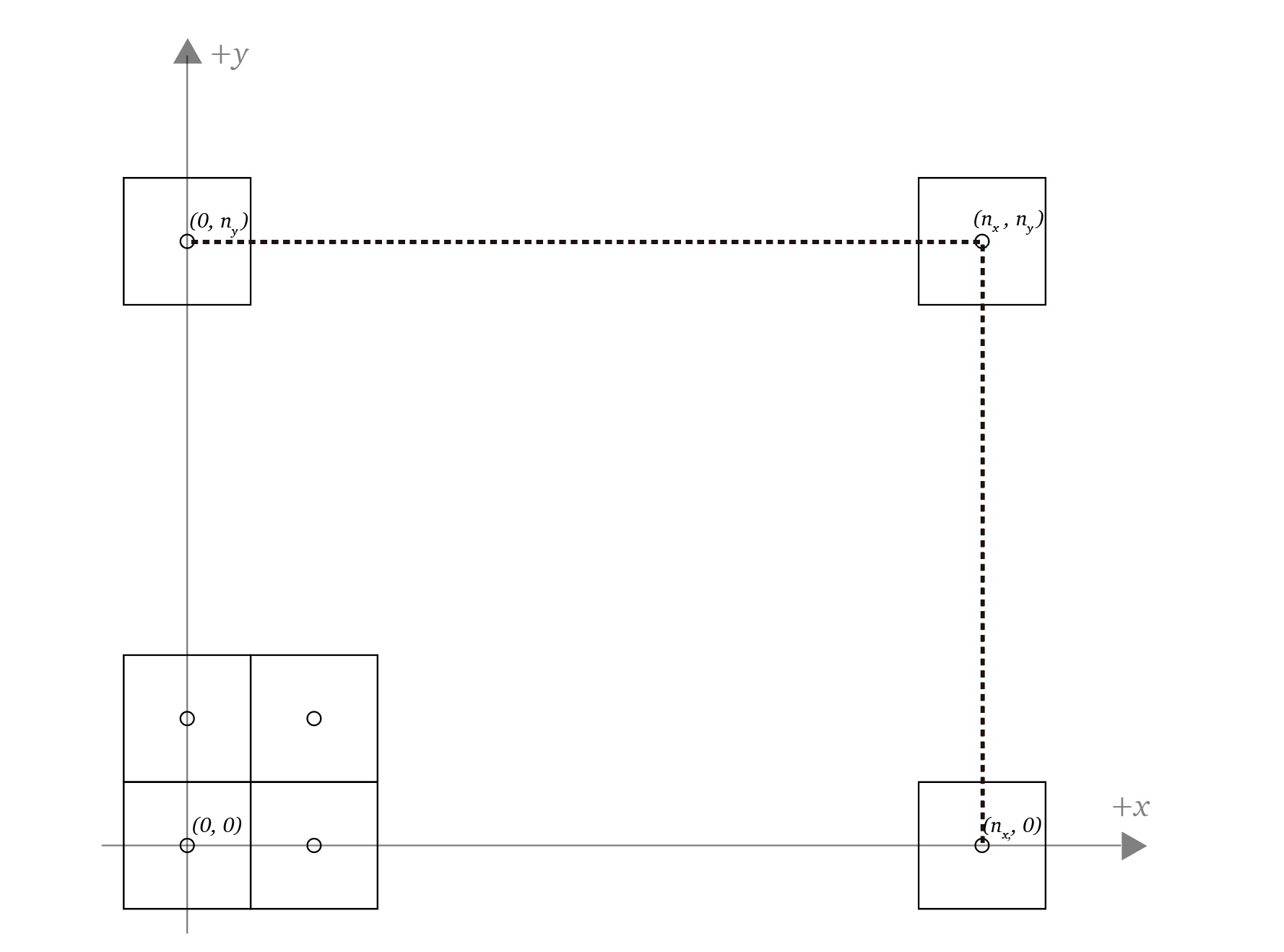


After the projection step, every point of the scene sits in normalized device coordinates, the cube $[-1, 1]^3$. The renderer still has to place those points on the actual screen, a grid of $n_x \times n_y$ pixels. The viewport transform performs that mapping:
$$ \mathbf{v}_{screen} = \mathbf{M}_{vp} \mathbf{v}_{ndc} $$
The mapping rules are simple. A point with $x = -1$ lands on the left edge of the screen, and $x = 1$ lands on the right edge. Similarly, $y = -1$ and $y = 1$ land on the bottom and top edges. The $z$-coordinate points into the screen, so it has no position in the 2D image and is ignored by the mapping.
Pixel Centers and the Half-Pixel Offset
The endpoints of the $x$ mapping are not $0$ and $n_x$, but $-0.5$ and $n_x - 0.5$. The offset comes from how pixels are defined: the coordinate $(0, 0)$ maps to the center of the bottom-left pixel, so the left edge of the screen sits half a pixel before that center (see Rendering ). The viewport transform preserves the same convention.
Linear Interpolation
The mapping is linear, so a single linear interpolation parameterizes it:
$$ f(x) = out_{lo} + (out_{hi} - out_{lo}) \frac{x - in_{lo}}{ in_{hi} - in_{lo} } $$
For the $x$-coordinate the values are:
- $out_{lo} = -0.5$
- $out_{hi} = n_x - 0.5$
- $in_{lo} = -1$
- $in_{hi} = 1$
Substituting them into the interpolation formula gives the screen $x$-coordinate:
$$ \begin{align*} x_{screen} &= -0.5 + n_x \frac{x_{ndc} + 1}{2} \\ &= -\frac{1}{2} + \frac{n_x}{2}x_{ndc} + \frac{n_x}{2} \\ &= \frac{n_x}{2}x_{ndc} + \frac{n_x - 1}{2} \end{align*} $$
The screen $y$-coordinate follows the same derivation with $n_y$:
$$ y_{screen} = \frac{n_y}{2}y_{ndc} + \frac{n_y - 1}{2} $$
Both mappings are linear in their coordinate, so they fit into a single matrix. The $z$-coordinate passes through unchanged, since it carries depth for hidden-surface removal rather than a screen position:
$$ \mathbf{M}_{vp} = \begin{bmatrix} \frac{n_x}{2} & 0 & 0 & \frac{n_x - 1}{2} \\ 0 & \frac{n_y}{2} & 0 & \frac{n_y - 1}{2} \\ 0 & 0 & 1 & 0 \\ 0 & 0 & 0 & 1 \end{bmatrix} $$
Key Takeaways
| Concept | Formula | Takeaway |
|---|---|---|
| Viewport transform | $\mathbf{v}_{screen} = \mathbf{M}_{vp} \mathbf{v}_{ndc}$ | Maps the NDC cube onto the pixel grid, the final step before rasterization. |
| Half-pixel offset | $out_{lo} = -0.5$, $out_{hi} = n_x - 0.5$ | Pixel $(0, 0)$ is the center of the bottom-left pixel, so the screen edge sits half a pixel outside it. |
| Screen $x$ | $x_{screen} = \frac{n_x}{2}x_{ndc} + \frac{n_x - 1}{2}$ | Linear interpolation of $[-1, 1]$ onto $[-0.5, n_x - 0.5]$. |
| Depth passthrough | $z_{screen} = z_{ndc}$ | The $z$-coordinate keeps its value for depth testing and is not mapped to a pixel position. |